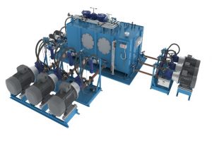
Solid Edge is a portfolio of affordable, easy-to-use software tools that addresses all aspects of the product development process–3D design, simulation, manufacturing, data management and more. Solid Edge combines the speed and simplicity of direct modeling with the flexibility and control of parametric design – made possible with synchronous technology.

Solid Edge
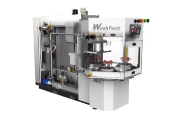
Advanced technology brings generative modeling, additive manufacturing and reverse engineering capabilities to Solid Edge. Enabled by unique Siemens convergent modeling technology, these capabilities work alongside traditional Solid Edge editing tools to seamlessly integrate existing products into your development process.
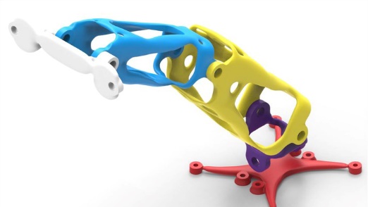
Generative Design
Supplementing powerful design tools with topology optimization, generative design speeds creation of lighter components perfectly suited for immediate manufacture via today’s additive processes. Or use Solid Edge to further refine the shape for more traditional manufacturing
Convergent Modeling
Solid Edge allows you to incorporate mesh models into the design workflow to create real designs. You can also seamlessly combine traditional “b-rep” solid models with triangular mesh models without time-consuming and error-prone conversions. Convergent Modeling by Siemens allows for traditional b-rep operations on digitally scanned 3D data and models born out of generative design, reducing rework while supporting modern additive manufacturing processes for complex shapes.
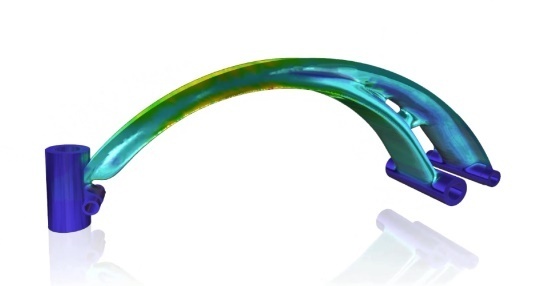
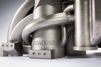
Additive manufacturing solutions
Solid Edge enables you to create world class products using the latest additive manufacturing and 3D printing techniques. Generative design combines powerful design tools with topology optimization, speeding the creation of lighter components perfectly suited for immediate manufacture via additive processes. Helps prepare geometries for Additive Manufacturing Techniques & Outputs models in 3D Printer machine readable format.
Reverse Engineering
In conjunction with powerful 3D design tools, Solid Edge delivers smart functionality to work with mesh, or triangle-based data. Bodies can be imported from other systems, digitally scanned or products of a generative design analysis. All of these come in as a mesh of triangles (or facets) and in many cases require further design modification.
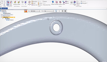
Solid Edge provides intuitive mesh cleanup tools to remove any errors that may have resulted from the import process, allowing designers to obtain a workable set of triangles. Once you have a sound mesh, regions can be identified and created, and those regions can be further extracted as surfaces and edited using traditional surface modeling tools.
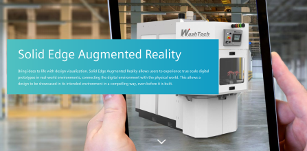
Augmented Reality
Bring ideas to life with design visualization. Solid Edge Augmented Reality allows users to experience true-scale digital prototypes in real-world environments, connecting the digital environment with the physical world. This allows a design to be showcased in its intended environment in a compelling way, even before it is built.
Sheet Metal Design
To meet unique sheet metal design challenges, like manufacturability, Solid Edge streamlines the entire sheet metal product development process, from CAD design through flat pattern and drawing development. Unlike general purpose CAD tools, Solid Edge includes sheet metal-specific features, like Emboss, Dimple, Drawn Cutout, Bead, Contour Flange, Straight Brake and Etch. And with integrated applications for analysis, NC programming, and related tasks, Solid Edge helps you speed design time, improve quality, and reduce costs.
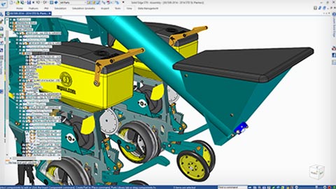
Modular Plant Design
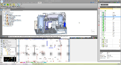
From rudimentary 2D pipe planning to full-scale 3D piping systems, Solid Edge modular plant design solutions streamline workflow processes. Linked 3D piping, support for piping and instrumentation diagrams (P&ID) and Isogen® output ensure that your products are designed right—the first time, and every time. These software modules allow users to easily capture design intent/logic in a 2D schematic, then develop 2D P&IDs into a comprehensive 3D model of a process plant.
Photo Realistic Rendering
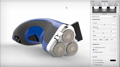
A picture of your finished product can help you communicate your design to both internal and external stakeholders. The beauty of rendering is that you can generate realistic looking photo quality images before you even cut the first piece of material to manufacture your product.
Solid Edge Simulation
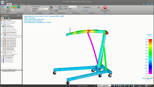
Solid Edge Simulation Built-in finite element analysis (FEA) allows design engineers to digitally validate part and assembly designs within the Solid Edge environment. Solid Edge Simulation significantly reduces the need for physical prototypes, which lowers your material and testing costs, and saves design time.
-Capabilities – Motion , Stress , Vibration, Buckling & Thermal Simulation.
Flow simulation for computational fluid dynamics (CFD) in Solid Edge
Simcenter FLOEFD for Solid Edge supports flow simulation with an embedded CFD simulation tool for easy, fast and accurate fluid flow and heat transfer analysis.
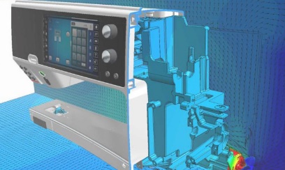
Fully embedded in Solid Edge, FLOEFD enables design engineers to frontload CFD, or move simulation early into the design process where it can help examine trends and eliminate less desirable design options.
Technical Publications
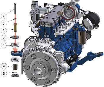
The ability to clearly communicate the correct manufacturing, installation and maintenance procedures for your designs is essential to the performance of your products and the success of your business. Using Solid Edge technical publications solutions, your designers can quickly create many types of technical documents—from simple illustrations for end user manuals to interactive 3D technical documents for manufacturing and service. You can reduce the need for specialist technical authors or external services and produce top quality documents in-house.
Frequently Asked Questions
What is SOLID EDGE CAD?
SOLID EDGE CAD is a feature-rich 3D computer-aided design software developed by SIEMENS PLM Software for mechanical design and engineering.
What are the key features of SOLID EDGE CAD?
Key features include parametric modeling, synchronous technology, assembly design, drafting, and integrated simulation capabilities.
Does SOLID EDGE CAD support direct modeling?
Yes, SOLID EDGE CAD includes synchronous technology for direct modeling, allowing users to edit 3D models regardless of their design history.
Can SOLID EDGE CAD import and export various file formats?
Yes, SOLID EDGE CAD supports importing and exporting a wide range of file formats for interoperability with other CAD software and collaboration purposes.
Is SOLID EDGE CAD suitable for small and medium-sized businesses?
Yes, SOLID EDGE CAD offers scalable solutions tailored to the needs of small and medium-sized businesses, providing cost-effective options for product design and development.
Does SOLID EDGE CAD offer cloud-based collaboration?
Yes, SOLID EDGE CAD provides cloud-based collaboration features, enabling teams to work together on design projects in real-time from anywhere with an internet connection.
Are training programs available for SOLID EDGE CAD users?
Yes, SIEMENS PLM Software offers training programs and resources for SOLID EDGE CAD users to enhance their skills and productivity.
What industries typically use SOLID EDGE CAD?
SOLID EDGE CAD is used across industries such as machinery, consumer products, electronics, and industrial
