The days of isolated engineering silos are a thing of the past. Modern product development is sophisticated and complex at the same time. They demand across mechanical, electrical, and software domains, seamless collaboration.
If these disciplines work in fragmented environment, they result in costly errors late in the design cycle and friction with slower time-to-market. A unified, multi-disciplinary engineering platform will significantly minimize these issues. That’s where Siemens NX comes into play.
It offers a unified, multi-disciplinary engineering platform that
- Provides a unified data model. All mechanical parts, electrical components, and simulation meshes reside within a single environment. That are linked and managed by the central thread of Teamcenter PLM.
- Allows co-design and co-simulation, with continuous validation. This in turn allows mechanical engineers, electrical designers, and simulation specialists to work on the same product data concurrently.
MECHANICAL DESIGN – MASTERY IN NX
Mechanical structure remains the foundation of any physical product. NX Software offers the most robust and flexible tools for the most complex geometry creation. This will enable engineers to stay focused on performance and innovation.
The following details the tools.
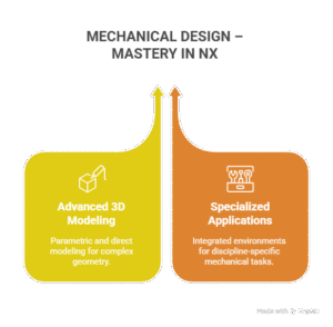
ADVANCED 3D MODELING & DRAFTING
NX offers for both parametric (feature based) and direct (synchronous technology) modeling powerful capabilities. Mechanical engineers can now quickly iterate detailed sheet metal components and large assemblies, on complex surfaces.
The NX software can also handle complex geometry common in specialized domains. Like for instance, aerospace structures, turbine blades, and intricate manifold systems.
SPECIALIZED MECHANICAL APPLICATIONS
Siemens NX provides beyond core CAD integrated environments for discipline-specific tasks.
Like,
SHEET METAL DESIGN:
- Includes automated tools for creating flanges, bends, and cutouts.
- Ensures the model is always manufacturable, with accurate flat patterns generated instantly.
WELD DESIGN AND DOCUMENTATION:
- Includes tools to specify directly on the 3D model, weld types, sizes, and locations.
- Generates compliant documentation. Also, communicates clear requirements to manufacturing.
DESIGN FOR MANUFACTURING (DFM):
- Includes built-in checks and validation tools.
- Assess through these tools the manufacturability, assembly sequence, and cost implications of the mechanical design from the earliest stages.
INTEGRATING THE INTELLIGENCE: ELECTRICAL DESIGN IN NX
Electrical components (harnesses, PCBs, sensors) are the ‘intelligence’ of the modern product. Siemens NX ensures the intelligence integrates with the physical chassis perfectly.
NX ROUTING AND HARNESS DESIGN
The most significant integration point is electrical harness routing. The electrical team using NX Software can route complex bundles of wires and cables directly within the 3D mechanical model.
COLLISION DETECTION: Real-time collision checks
- Ensure the harness avoids interference with mechanical parts. Like engine block, moving linkages.
- Eliminate a common source of late-stage physical prototyping failures.
AUTOMATIC LENGTH CALCULATION: Precise 3D routing
- Calculates automatically accurate wire lengths, essential for manufacturing.
- Eliminates costly scrap material.
CO-DESIGN: Changes to a mechanical bracket
- Flags instantly the electrical team.
- Ensures the harness design is updated before the mechanical model is released.
PCB DESIGN INTEGRATION
The PCB (Printed Circuit Board) is critical. Siemens NX facilitates electromechanical collaboration on the PCB.
MCAD / ECAD SYNCHRONIZATION: NX Software integrates with leading ECAD tools like Mentor Graphics. This allows
- Mechanical engineers to check component clearances, thermal dissipation, and mounting points on the board layout.
- Electrical engineers to focus on circuit function.
THERMAL SIMULATION FEEDBACK: Mechanical team can
- Run quickly the thermal simulations based on the placement of heat-generating electrical components.
- Ensure the adequate cooling is provided by the design.
VALIDATION THROUGH SIMULATION: NX SIMULATION
Simulation is no longer a post-design check. It’s an inherent part of the design process today. The unified environment of NX Simulation accelerates validation by linking analysis directly to the design geometry.
INTEGRATED CAE FOR FASTER ITERATION: NX Simulation
- Provides a full suite of Computer-Aided Engineering tools (FEA, CFD, Kinematics), all residing within the NX interface.
- Eliminates through tight coupling the need for data translation (which introduces errors) between the CAD and CAE domains.
GENERATIVE DESIGN & TOPOLOGY OPTIMIZATION:
- Simulation drives the design;
- Engineers can define performance criteria (loads, constraints); and
- NX generates automatically optimal mechanical geometry. This is subsequently validated using the same simulation tools.
MULTI-PHYSICS SIMULATION:
- Modern products require analysis of the interaction between physics domains (like fluid dynamics affecting structural integrity, or thermal stress).
- NX allows setting-up and solving these complex coupled multi-disciplinary engineering problems in one place.
SPECIALIZED SIMULATION FOR ELECTOMECHANICAL SYSTEMS
NX Simulation’s true power lies in validating the integrated system.
MOTION SIMULATION: Is used to
- Test the kinematic behavior of complex assemblies. Like robotic arms, landing gear.
- Identify instantly interference. This ensures the electrical harness (routed in 3D) does not pinch or tear during motion.
THERMAL MANAGEMENT: NX Simulation
- Models accurately airflow and heat transfer.
- Validates that the mechanical chassis design can effectively cool the battery packs and control electronics.
CONCLUSION
Siemens NX by facilitating a truly concurrent engineering environment empowers distributed teams to innovate faster and lower development costs. They reduce physical prototypes and ensure the final product meets stringent performance and safety norms.
Organizations can by leveraging CJ Tech’s proficient NX Software capabilities drive multi-disciplinary engineering success.
FAQs
1. In what way is a unified platform like NX Software better than using separate, best-in-class tools for each discipline?
Using separate tools creates silos. This leads to data inconsistencies; integrated errors; and slow iteration cycles. NX Software on the other hand, solves this problem by centralizing the data. This ensures that changes made by the mechanical team are instantly visible and traceable for the simulation and electrical teams.
2. Does NX replace dedicated electrical design (ECAD) software?
No. NX Software is not intended to fully replace the core functionality of dedicated ECAD tools. Instead it integrates seamlessly with them (like Mentor Graphics).
This integration allows:
- Mechanical engineers to check component clearances and thermal impacts on the PCB layout in 3D; and
- Electrical engineers to focus on circuit function in their specialized ECAD environment.
3. How does Siemens NX ensure the electrical harness fits the mechanical enclosure?
NX uses NX Routing and Harness Design Tools. Electrical engineers using it route the harness directly within the 3D mechanical assembly.
The system
- Performs real-time collision detection with mechanical parts.
- Calculates automatically precise lengths based on the 3D path.
They prevent fitment issues that otherwise would be discovered during physical prototyping.
4. How does NX Simulation accelerate the validation process?
NX Simulation is fully integrated with the CAD geometry. This eliminates the need for time-consuming data translation. That otherwise would require moving models between separate CAD and CAE tools. When the mechanical design is updated, the simulation model gets updated instantly. This allows for rapid, continual validation throughout the design process.